Opti
Design optimization of latticed bike saddles
Ongoing (Jan 2022 - Present)
Solo Project
Conceptualizing innovation for HP-NTU Digital Manufacturing Corporate Lab
Design Brief:
How can we utilize and promote the adoption of Digital Manufacturing, in particular Additive Manufacturing?
What are the key design freedoms that can be leverage on?
.jpg)
Overview
With additive manufacturing, greater degrees of design freedoms can be afforded via design optimization and mass customization of part geometries. One way to leverage the geometrical and hierarchical complexities of additively manufactured parts is the manufacturing of functionally-graded lattice structures – a tall order for conventional manufacturing technologies.
Ranging from engineering-intensive industries in aerospace and automotive to everyday consumer products such as sporting goods and soft ergonomics equipment, there exists a great potential for applications of lattice structures as they are increasingly utilized for achieving goals in load distribution, material reduction, high strength-to-weight ratio, energy absorption, impact protection, and more. Yet, the selection and optimization of suitable unit cell types and strut diameters to generate lattice structures for improving mechanical performance of specific applications remains a challenge for engineers due to the lack of customizable computational design support tools integrating domain experts’ knowledge and past empirical outcomes across the stages of the engineering design process.
To promote the utilization of additively manufactured products with lattice structures, a digital design workflow synthesizing parametric design, simulation, and optimization to generate lattice structures, by considering specific additive manufacturing constraints, is proposed as a design support tool to aid in decision-making.
Identifying gaps in existing approaches for designing lattice structures
-
High barriers to entry and limited flexibility for customization to specific applications exist within commercialized design tools in generating, implementing, and evaluating lattice structures to part geometries. There is also a limited selection of cell types available, with a lack of simulation integration and optimization capabilities.
-
Producing latticed products via conventional manufacturing methods is a tedious and nearly impossible method due to the complex technical feasibility, long quality control time and high costs involved.
-
There is no well-defined standard for classifying lattice structures to aid in the design, selection, and assessment of cellular patterns that might work best for optimizing functions of specific applications.
To tackle these problems, it is crucial to understand the impact of specific design parameters on the performance of lattice structures, so as to better inform engineers in the selection of suitable unit cell types and strut diameters for specific applications, or recommend plausible combinations to optimize desirable mechanical performance or other function goals. Additive manufacturing constraints should also be considered, specifically the minimum unit cell gap and minimum strut diameter d, to ensure manufacturability and printability of latticed products via Multi Jet Fusion (MJF).
Methodology
Grasshopper3D, a visual programming platform hosted in Rhinoceres3D, is used to integrate the constraints into the workflow. With Grasshopper3D, base models can be easily parametrized to control design variables and allows the visualization of multiple design iterations, simulated and optimized via algorithimic methods. A change in the design parameters will reflect the real-time impact on the targeted model, making it a user-friendly interface to run iterations on. Plug-ins such as Weaverbird, Pufferfish, Karamba3D and Octopus were used in the workflow. The workflow is examined through a case study of a bike saddle for fabrication via MJF. The material used will be BASF Ultrasint™ TPU01. Other constants of the study are the arbitrary target areas of localized density, the total number of unit cells, and the load applied as exerted by the average weight of a normal rider.

Stage A: Importing 3D model
A 3D saddle model is imported and divided into its respective feature surfaces (e.g. top surface, bottom surface, and side surfaces) for ease of integration into the workflow.

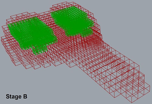
Stage B: Formation of inner lattice structures (Selection and mapping of main pressure areas)
A database of lattice unit cell types x (Simple Cubic (SC), Body-centered Cubic (BCC), Face-centered Cubic (FCC)) is selected. Twisted boxes of the lattices are then created and trimmed accordingly to the model’s boundaries. The lattice unit cells will be morphed into these twisted boxes. Next, areas that are expected to experience large stress values within the geometry are identified to occupy a higher localized density of lattices by subdividing the lattices within these volumes into four unit cells each. This creates a denser region of lattice configuration, functionally grading the overall model.

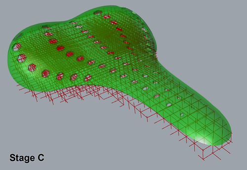
Stage C: Formation of shell
The shell of the model is created by offsetting the original mesh and thickening it into a solid shell. Perforations have been added considering the Design for Additive Manufacturing heuristics, to prevent generating hollow closed structures during printing. Alternatively, the shell may be manufactured separately and assembled post-printing to better customize textured surfaces.

Stage D: Simulation and assessment of mechanical behaviour
A static structural simulation using finite element analysis (FEA) is performed to predict the mechanical performance of the model. The lattices are redefined as beam line segments with solid cross sections. Supports are located in an array at the bottom of the saddle with a constant normal load in the z-direction is applied at the top. The maximum displacement and mass of the analyzed model are obtained as a direct result of the analysis. The maximum stress experienced by the struts is obtained by dividing the maximum compressive force exerted on the latticed model with the cross-sectional area of the struts.

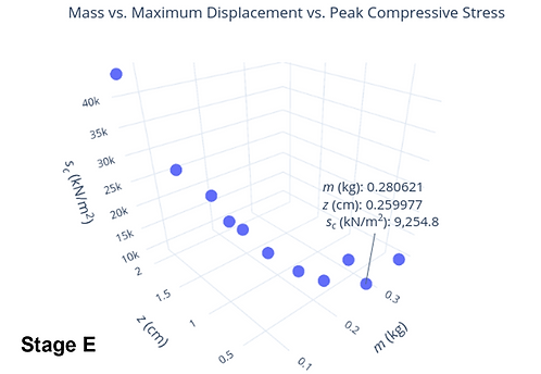
Stage E: Optimization for design iterations
The model undergoes iterations via the HyPE genetic algorithm and mutation to evaluate all design possibilities within the range of the design parameters chosen to minimize the mass (m), maximum displacement (z), and peak stress (sc) experienced by the latticed saddle. Each design alternative can be divided into multiple design parameters that inform its geometrical features. Solutions are then generated by iterating all possibilities within the ranges of the design parameters given by the human designer. The scatter plot corresponding to the objective function values obtained, in addition to the visual programming workflow, alleviates the invisibility of iterations as design alternatives can be quickly visualized and compared when a set of design parameters is selected.

Design Iterations and Preliminary Results
The simulation outcomes of the six possible combinations of boundary conditions, based on the lower and upper limits of the strut diameter for each unit cell type studied, were recorded in terms of their masses, maximum displacements, peak compressive forces and stresses experienced, and the minimum gap of the smallest unit cell. The masses of the simulated models is within a reasonable range of conventional bike saddles. All models satisfy the minimum unit cell gap constraint, implying that the subsequent optimization which includes the intermediate combinations of the design parameters will produce models that satisfy the same constraint as well. The simulation results indicated that the hybrid latticed saddle possess better energy absorption capability than the uniform latticed saddle.
At the Pareto front, the set of non-dominated solutions can be observed, giving users more confidence in evaluating and selecting a combination that best fits their objectives. Correlations among x, d, m, z, s experienced by the struts can be identified and evaluated from the simulation and optimization results as well, providing insights into their influences predicting the behaviors of lattice structures. Through the FEA simulation and optimization, the compressive strength characteristics of the lattice structures can be inferred. It can be deduced that the FCC-filled saddle exhibiting optimal stretching-dominant behavior is the best choice to optimize energy absorption as it is more likely to demonstrate uniform stress distribution and possess better mechanical compression properties. This is also in agreement with literature with regards to the performance of the three unit cell types and their respective Maxwell stability number, as calculated from their number of struts and nodes. It is feasible to preliminary assume that outcomes of the workflow are reliable and provide insights for engineers when optimizing products with lattice structures possessing an acceptable energy absorption ability.

Future scope (in progress)
More work can be done to verify and strengthen the results beyond quasi-static compression loading on the model, such as studying failure under dynamic loading, experimental validation, and more. Other factors that can improve the reliability of the optimization include factoring in the uncertainty of defective prints, material costs, and overall production time required to estimate the economics and manufacturing timelines of fabricating products with lattice structures.
The workflow can be scaled to generate solutions for other products and case studies, depending on the evaluation criteria of specific applications. I am also looking to improve the optimization search with machine learning approaches to reduce the computation time, expand the design space beyond what was provided, and run iterations with a wider range of design parameters.
